GAS COMPRESSION & VAPOR RECOVERY
VAPOR RECOVERY
Eagle is a leader in the design and manufacture of custom VRU packages for the oil and gas industry. Our VRU units are custom-built to suit any application and can be tailored to meet the most stringent of customer requirements in regards to Safety, Performance and Equipment Specification.
The purpose of a VRU package is to control the vapor space pressure in facility storage tanks, flare knockouts, still columns, gas boots or any other oil and gas equipment where critical low pressure suction control is required. The VRU will control the suction pressure by removing any excess gas and compressing it so that it can then be sent to a sales compressor or some other location on site where the gas can be recovered.
In the past these gas sources may have been vented or flared, but with new environmental rules and government directives enforcing the recovery of fugitive emissions. There has now been a shift towards recovery and compression.
Let Eagle custom engineer a VRU package for your application and put our knowledge and experience to work for you.
CAPABILITIES
Typical HP range
2HP – 200HP
Service
Sweet
Sour
High S.G, H2S, CO2, and water saturated
Driver Options
Electric
Hydraulic
Compressor Manufacturer
Rotary Vane: Utile, RoFlo
Screw: Gardner Denver
Reciprocating: Blackmer
VRU COMPRESSOR SELECTION
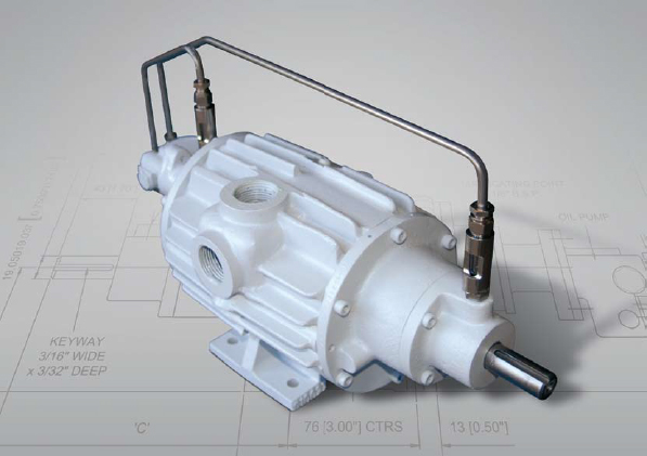
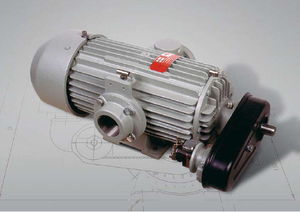
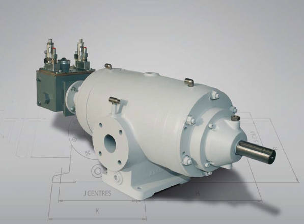
The preferred compressor selection for our Eagle VRU packages is the Rotary Sliding Vane compressor. These compressors are industry proven to be the most reliable, cost effective, and maintenance free compressor for the harshest of VRU applications.
Where screw compressors and Recip compressors generally struggle with oil dilution and reliability issues, the robust nature of the Vane compressor is the first choice for VRUs.
Eagle is an Authorized Canadian Utile Distributor
L-SERIES AIR COOLED COMPRESSORS
Utile Vane Compressors for Low Pressure Applications
(0 psig – 30 psig Discharge)
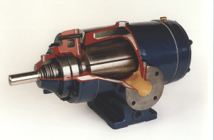
UTILE AIR-COOLED GAS COMPRESSORS
- Ball bearing for axial location and thrust
- Heavy duty roller bearings at both ends
- Balanced rotating parts for reduced vibration
- Low running speeds
- Blade wear checking ports
- Kevlar blades for extended life
- Bearing housings fully sealed from gas
- Easy access from non drive end for blade change when direct coupled
- Flow rate: up to 500 MSCFD
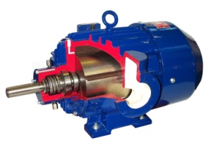
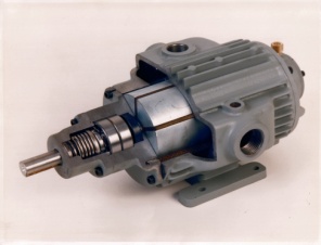
HD SERIES WATER COOLER COMPRESSORS
Utile Vane Compressors for Medium Pressure Applications
(0 psig – 60 psig Discharge)
UTILE WATER-COOLED GAS COMPRESSORS
- Ball bearing for axial location and thrust
- Heavy duty roller bearings at both ends
- Balanced rotating parts for reduced vibration
- Low running speeds
- Blade wear checking ports
- Kevlar blades for extended life
- Bearing housings fully sealed from gas
- Easy access from non drive end for blade change when direct coupled
- Maximum casing pressure: 125 PSIG for 2 staging
- Maximum flow rate: 1 MMSFD
- Designed to handle sour gas
ROTARY VANE COMPRESSOR SPECS AND PERFORMANCE:
Vane-LG Series Specs
Vane-HD72-550 Specs
Vane-L95HP-L320HP Specs
FUGITIVE EMISSION RECOVERY
Recip Rod Packing, Distance Piece and Centrifugal Shaft Seal Emission Recovery
Eagles Emission Capture compressors are a proven solution for recovering sweet and sour vent gas from reciprocating compressor rod packing, distance piece purges or centrifugal compressor shaft seals.
As part of the Government of Alberta’s Climate Leadership Plan, the AER (Alberta Energy Regulator) was tasked with developing requirements to reduce methane emissions from upstream oil and gas operations by 45 percent relative to 2014 levels by 2025. To achieve this new goal an updated edition of Directive 060: Upstream Petroleum Industry Flaring, Incinerating, and Venting was created which includes new requirements for the capture and recovery of the above fugitive emissions.
Whether being installed into new equipment or retrofitted into existing equipment in the field. Eagle emission capture compressors are helping industry become compliant and recover nuisance emissions.
CASING GAS RECOVERY
FUEL CONDITIONING UNIT (FCU)
Eagle casing gas Fuel Conditioning Units were first put into service in Alberta over 15 years ago. As of 2019 there are over 2000 units operating and recovering vented casing gas throughout Alberta and Saskatchewan.
The FCU unit takes annulus gas from the well at <5psig suction pressure and compresses the gas to over 120psig at which point the gas is conditioned, dried and metered for use on site or sold to commercial pipelines. The condition of the gas is dry to less than 4lbs H2O/MMSCd (-32C@100psia) and is pipeline quality gas when it leaves our package.
Eagle FCU units will help you:
- Comply with the new venting regulations of Directive 060: Upstream Petroleum Industry Flaring, Incinerating, and Venting
- Offset or eliminate Propane usage
- Generate revenue from a previously vented gas source
- Enhance and improve oil production on heavy oil wells
FUEL CONDITIONING UNIT-VAC (FCU-V)
The second evolution of the FCU unit is the FCU-V. This package has the same design as the standard FCU in regards to the compressor and dryer system but it does have one major difference in that the suction of the compressor is designed to pull the well into vacuum.
It has been found that on some heavy oil wells the oil flow is negatively affected by pressure on the annulus. By decreasing the pressure to a vacuum, significant oil production gains as well as 100% gas recovery can be achieved.
VAC COMPRESSOR ADVANTAGES
- Enhanced oil production
- 100% gas recovery
- Reduction in well servicing
- Reduction in GOR testing
- Extended Pad life
- Increased down hole pump efficiency
- Fluid level increases in well
GAS DRYER
EGDR GAS DRYERS
Natural gas usually contains significant quantities of water vapor. Changes in temperature and pressure condense this vapor altering the physical state from a gas to a liquid. This liquid water must be removed in order to protect processing and fuel gas systems from corrosion and damage.
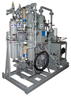
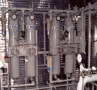
Eagle EGDR gas dryers have been specifically designed to remove this water vapor through a regenerative pressure swing dual tower design. Regenerative dryers provide an economical and efficient way of drying gases.
Eagle has multiple standard dryer sizes available to suit any flow rate from 30mscfd – 2000mscfd.
Each Dryer comes equipped with:
- Dual Regenerative Drying Towers
- Inlet coalescing filter with auto drain
- Outlet particulate filter
- Sequencing control panel
- Inlet and outlet switching valves
- Tower PSV’s
- Tower Pressure Indicators
- Purge Orifice and control valve
- Instrument regulator
- System Kimray Back pressure valve
- Rotary Gas meter
FEATURES OF THE EGDR GAS DRYER
- Reduces H20 content to < 4 lbs./MMSCF (-32C @100psia)
- Reduces “Heavy End” hydrocarbon content
- 200 PSI design pressure
- Low velocity for increased efficiency
- Low Pressure Drop design
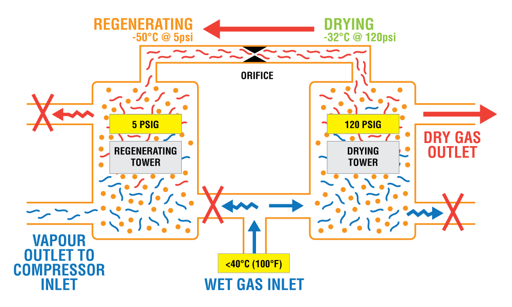
OPERATING PRINCIPLE
EGDR dryers operate with a dual tower regenerative Pressure swing design. One tower is used to dry the gas at high pressure while at the same time the second tower is regenerating the desiccant at low pressure. This swing in operating pressure as well as the alternating cycle back and forth from tower to tower is what creates a regenerative system that allows the desiccant to be reused continually instead of having to be replaced.
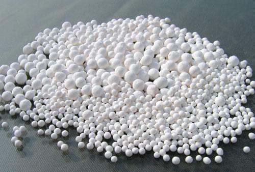
The system operates by passing moisture saturated gas over a dry desiccant medium in the first tower. In doing so, the water vapor is removed from the gas stream and is adsorbed to the surface of the desiccant bead in the tower. Eventually this desiccant bed becomes saturated and needs to be regenerated.
In the second tower the desiccant bed is saturated at the start of the cycle and needs to be regenerated. To achieve this we take a small portion of the dry high pressure gas from the top of the first tower and feed it down through tower two where this purge gas is allowed to expand due to the drop in operating pressure down to <5psig. At this low tower operating pressure the purge gas is extremely dry and easily desorbs the water from the surface of the desiccant bead which in turn dries the desiccant bed.
By alternating the towers back and forth from drying to regenerating, a fully regenerative cycle is achieved allowing continuous use of the dryer in even the harshest of applications.